In this section you will repeat the meaning of basic remote sensing terminology using the example of three satellites which we will continue to use in RESEDA, i.e., Landsat 8, Sentinel 2 and Sentinel 1. However, the shown methods in this online course are also adaptable to other satellite sensors, airborne imagery or close-ups by considering the respective sensor characteristics.
Non-Imaging vs Imaging Sensors
Non-imaging sensors, such as laser profilers or RADAR altimeter, usually provide point data, which do not offer spatially continuous information about how the input varies within the sensor’s field of view.
By contrast, imaging sensors are instruments that build up a spatially continuous digital image within their field of view, whereby they include not only information about the intensity of a given target signal, but also information about its spatial distribution. Examples include aerial photography, visible or near infrared scanner as well as synthetic aperture radars (SAR). All three satellite missions we will work with (Landsat 8, Sentinel 2 and Sentinel 1) are imaging sensors.
Passive vs Active Sensors
Anyway, there is a fundamental differentiation of remote sensing systems that we need to be aware of: passive and active sensors. This classification is based on the underlying recording principles, which are contrasted in the following:
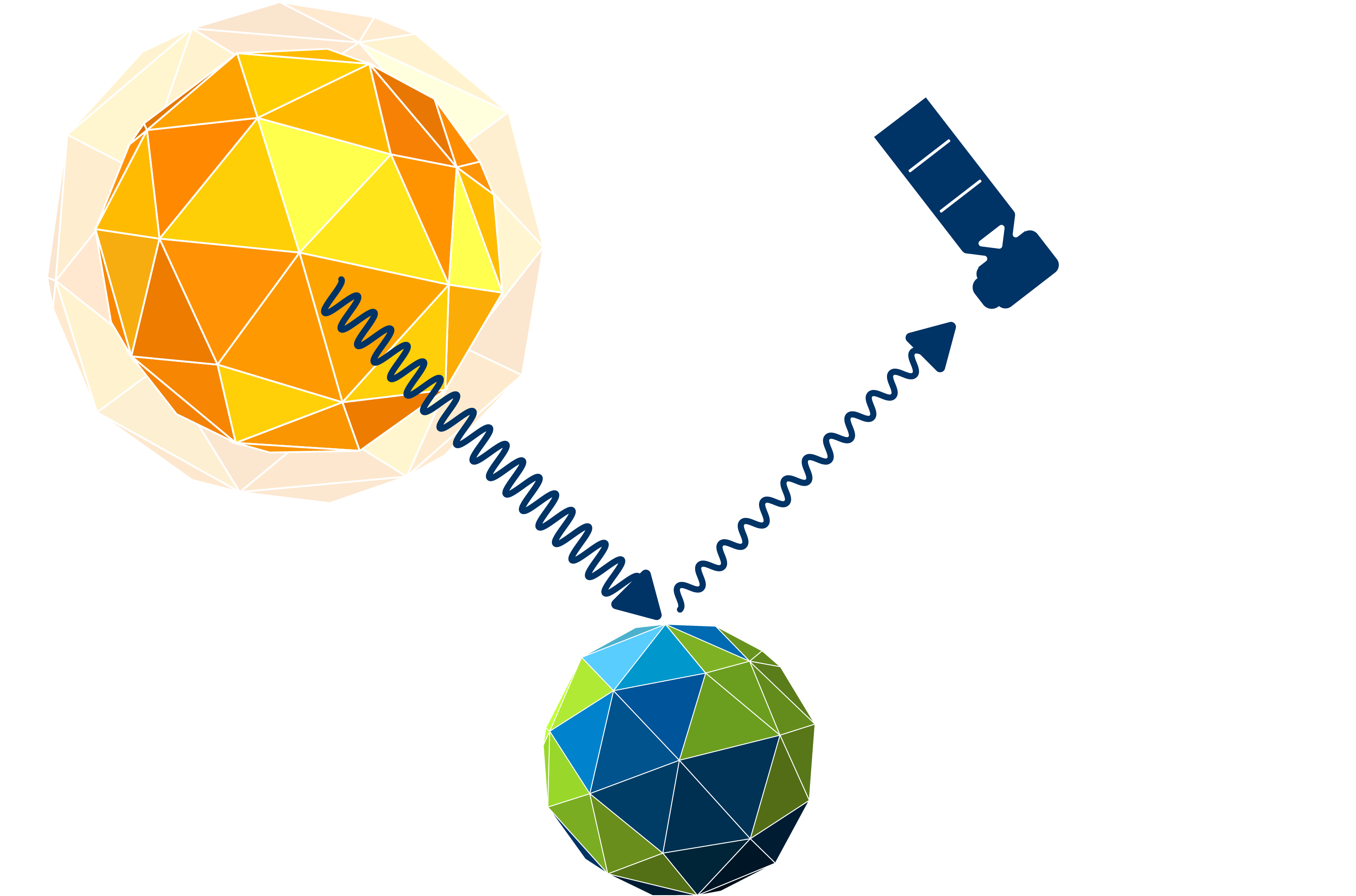
Passive sensors should be the more common of those two. Passive sensors measure solar light reflected or emitted from the Earth surfaces and objects.
These instruments primarily rely on short waved electromagnetic solar energy of the sun as the only source of radiation. Objects on the Earth’s surface react to this electromagnetic energy either with reflection, transmission, or absorption, depending on the composition of the object’s atoms. Passive sensors mainly capture the reflected proportion of the solar energy. Thus, they can only do their observation job when the sun is present as a radiation source – that is, only during the day. Anyway, since objects also partially absorb incoming solar light, there is a inherent radiation of these objects, which can be measured, for example, as thermal radiation.
Passive remote sensing imagery can be very similar to how our human eyes perceive land cover, which makes it easier for us to interpret the image data.
Unfortunately, there is one big limitation of passive systems: Due to the fact that the reflected electromagnetic radiation has to pass through the Earth’s atmosphere, the signal is strongly influenced by the weather and cloud conditions: Fog, haze and clouds render affected image information partially or completely useless, as electromagnetic energy is scattered by the large particles of dense clouds. This is where active sensors come into play.
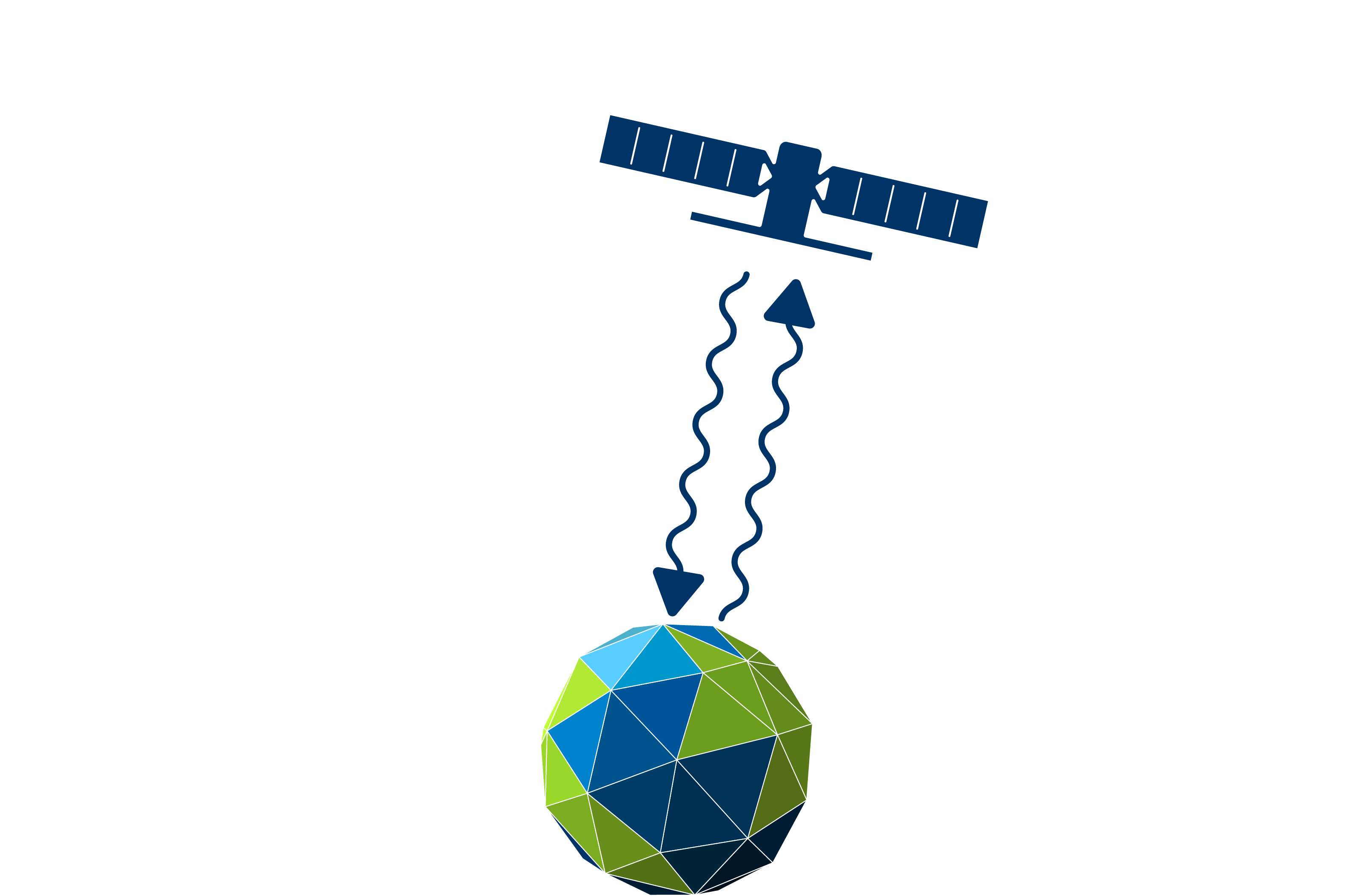
Active sensors emit their own electromagnetic radiation to illuminate the object they observe.
Active sensors send a pulse of energy at the speed of light to the Earth’s surface, that is reflected, refracted or scattered by the objects on the surface and the atmosphere. The recieved backscatter then gives information on land surface characteristics. There are many types of active sensors out there: RADAR (Radio Detection and Ranging), Scatterometer, LiDAR (Light Detection and Ranging), and Laser Altimeter. We will take a closer look at Sentintel 1, a SAR system (Synthetic Aperture RADAR), which is an imaging RADAR type working with microwaves, in the upcoming SAR chapters.
Images of active sensors are comparatively difficult to interpret: A SAR signal contains amplitude and phase information. Amplitude is the strength of the RADAR response and phase is the fraction of a full sine curve. In order to generate beautiful images out of these information, a more extensive preprocessing is often necessary, which we will do in SNAP.
Since no natural light source is required, active sensors are capable to emit and capture their signals regardless of daytime. In addition, many systems operate in the electromagnetic domain of microwaves, so their wavelength is large enough to be unaffected by clouds and other atmospheric distortions.
Imaging Sensor Resolutions
When working with imaging remote sensing systems, a distinction is made between four different resolution terms: geometric, spectral, radiometric and temporal. It is essential to know those resolutions in order to be able to assess whether the sensor system is suitable for your research question!
1. Geometric Resolution
A digital image consists of at least one matrix of integers values – the picture elements, or pixels. Each pixel contains information about a signal response from a small area on the land surface, e.g., reflectance or backscatter. The geometric Resolution describes the edge length of this area (usually in meters) and is determined by the sensor’s instantaneous field of view (IFOV). It determines which object sizes can still be identified in the image – the degree of detail, so to speak. The effects of geometric resolutions becomes evident when comparing different images, for example an airborne orthophoto (0.1 m), Sentinel 2 (10 m) and Landsat 8 (30 m) images:
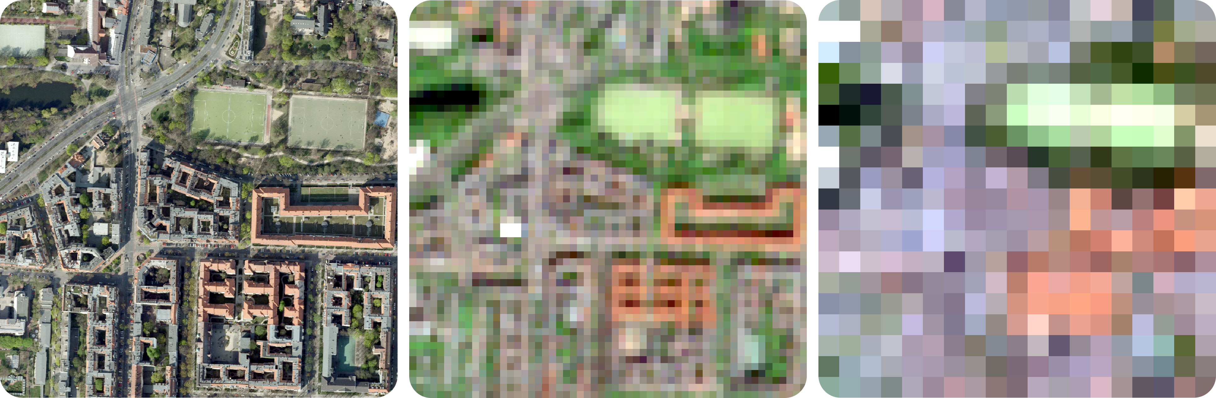
There are several synonyms commonly used for the term geometric resolution, e.g., spatial resolution, pixel size, pixel edge length, or ground sampling distance.
2. Spectral Resolution
We humans can only perceive the visible light around us, which is just a very small part of the available electromagnetic spectrum. Satellites, on the other hand, sense a much wider range of the electromagnetic spectrum and can provide us with information about processes that would otherwise be neglected.
Spectral satellite sensors measure the reflection from the earth’s surface in different wavelength areas of the electromagnetic spectrum, via so-called channels or bands. Each band can have a different bandwidth, i.e., the area scanned within the electromagnetic spectrum. The sensors concentrate the signals gathered within a band to one (pixel-) value via a sensor specific filter function.
However, spectral resolution describes the number of bands that the sensor senses. The purpose of multiple bands is to capture the differences in the reflection characteristics of different surfaces and materials within the electromagnetic spectrum.
Panchromatic systems have only one spectral channel with a large bandwidth usually from 0.4 to 0.7 μm. Due to this large bandwidth there is enough energy available to achieve high geometric resolutions. Various satellites additionally provide such a panchromatic channel, e.g., Landsat program, Quickbird-2 pan, and IKONOS pan.
Multispectral systems generally refers to 3 to 15 bands, which are usually located within the visible range (VIS, 0.4-0.7 μm), near-infrared (NIR, 0.75–1.4 μm), short-wavelength infrared (SWIR, 1.4–3 μm), mid-wavelength infrared (MWIR, 3–8 μm) and long wavelength/ thermal infrared (LWIR/TIR, 8–15 μm). Examples: Landsat program, Sentinel 2/3, SPOT, Quickbird, and RapidEye.
Hyperspectral systems (spectrometer) offer hundreds or thousands of bands with narrow bandwidths. A spectral resolution this high gives ability to distinguish minor differences of land cover characteristics, which in turn provides ability to address issues that could not be solved with multispectral data, e.g., mineral or building material classifications. There are some airborne spectrometers (AVIRIS, HySPEX, HyMAP) and to date only one operational satellite: Hyperion. Anyway, more spaceborne systems are already in the starting blocks, e.g., EnMAP and HyspIRI.
3. Radiometric Resolution
A digital sensor generally recognizes objects as intensity values, whereby it can only distinguish between dark and bright. The radiometric resolution refers to the ability to tell apart objects based on differences in those intensities. Thus, a sensor with a high radiometric resolution records more intensity levels or grey-scale levels. This property is expressed by the number of bits. Most satellite products have a bit depth of 8 to 16 bits, which means that they support 28(=256) or 216(=65536) different gray scale levels, respectively. A 1 bit image would be subject to a huge loss of information in comparison!
Those effects are easier to understand when looking at the image comparison below: An image with a bit depth of 1 contains only two gray scale levels (21=2), i.e., black and white. Using 2 bits double the number of available colors (22=4), which allows a few more details (as shown in the middle image). When using 8 bits, the image can draw from a whole color ramp ranging from black to white (dark to bright) comprising 256 grey scale values (28=256).
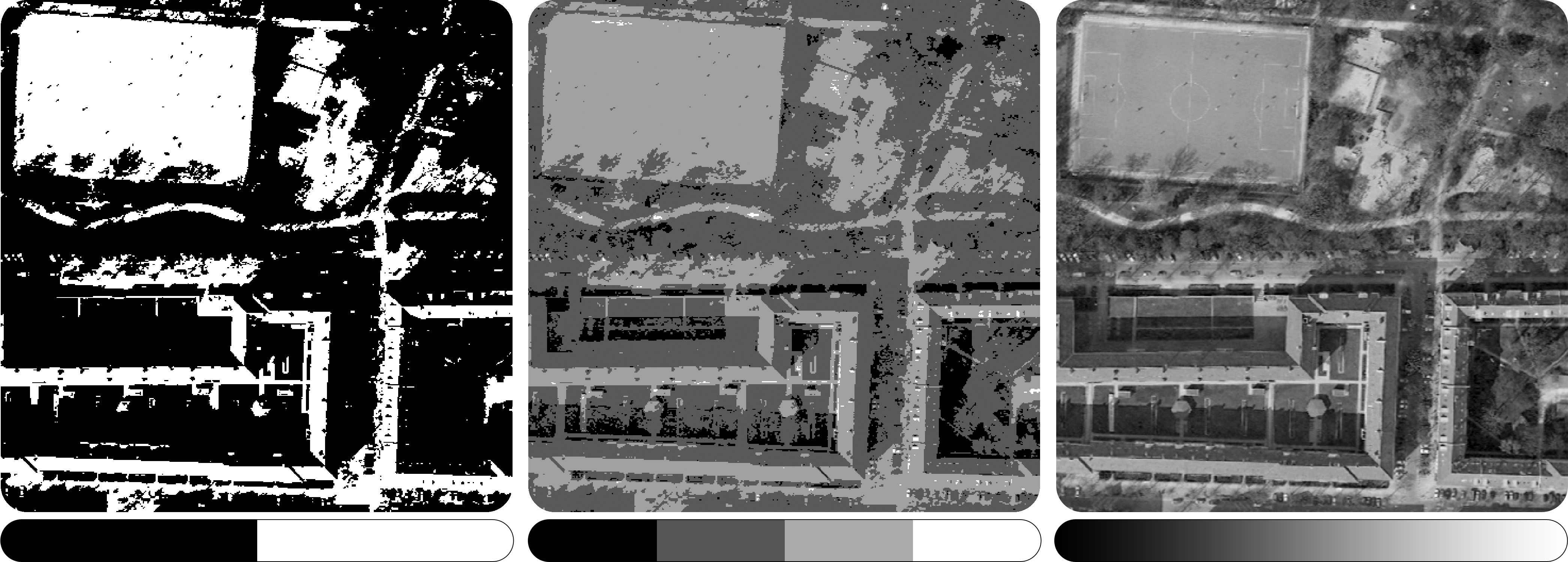
Human perception is barely sufficient to detect gray-scale differences beyond 8 bits in digital images. Nevertheless, machine learning algorithms often benefit from a finer differentiation of contrasts.
4. Temporal Resolution
The temporal resolution of a sensor is simply the distance of time (usually in days) between two image acquisitions of the same area. A high temporal resolution thus indicates a smaller time window between two images, which allows a better observation of temporally highly dynamic processes on the Earth’s surface, e.g., weather or active fire monitoring.
Most satellite sensors have a temporal resolution of about 14 days. Anyway, by using a satellite constellation of multiple sensors identical in construction the time between two acquisitions can be shortened. For example Planet Labs operates five RapidEye satellites, which are synchronized so that they overlap in coverage.
However, weather satellites are capable of acquiring images of the same area every 15 minutes. This can be explained by the different orbits of the satellites: geostationary and polar orbiting satellite systems.
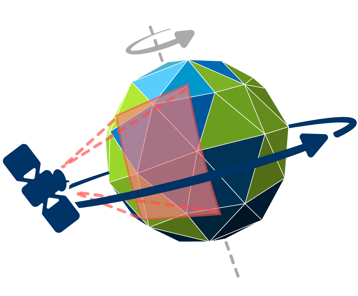
Geostationary sensors follow a circular geosynchronous orbit directly above the Earth’s equator. A geosynchronous system provides the same orbital period as the Earth’s rotation period (24 h), so it always looks at the same area on Earth, which it can observate at very high frequencies of several minutes. This rotation pattern is only possible at an altitude very close to 35.786 km, which generally results in a comparatively lower geometric resolution. Geostationary orbits are used by weather, communication and television satellites.
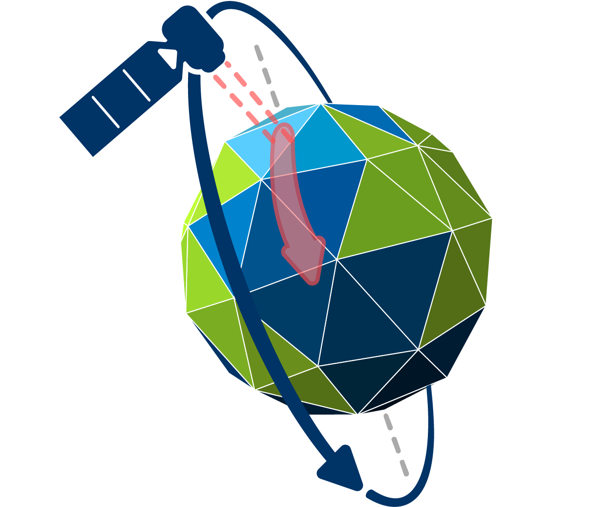
Polar orbiting satellites pass above or nearly above the poles on each orbit, so the inclination to the Earth’s equator is very close to 90 degrees. They fly at an altitude of approximately 800-900 km. The lower a satellite flies, the faster it is. That’s why an orbit takes only ~90 minutes. While flying from the north to south pole in 45 minutes, sun-synchronous sensors look at the sunlit side of the Earth (descending images). Moving from south to nord pole results in nighttime imagery (ascending images). On an descending flight, all polar orbiting satellites cross the equator between 10:00 am and 10:15 am (local time) to provide maximum illumination and minimum water vapor to prevent haze and cloud build-up. Due to their inclination, they map the entire surface of the earth within several days (~14 d) as the earth continues to rotate beneath them. The temporal resolution of polar orbiting satellites usually describes the repetition rate at the Equator. The coverage gets better at higher latitudes due to the poleward convergence of the satellite orbits.